Are you aware of the risks associated with misinterpreting electrical wiring colours in the UK? Understanding the colour coding system is crucial for safety in both domestic and commercial settings.
As someone involved in electrical work, whether you’re a professional electrician or a DIY enthusiast, it’s essential to know how to identify different wire colours and their functions.
This comprehensive guide will help you understand the UK’s electrical wiring colour system, covering single-phase and three-phase systems, and providing practical advice on how to avoid common mistakes that could lead to hazardous situations.
Key Takeaways
- Understand the UK’s electrical wiring colour coding system for enhanced safety.
- Learn to identify different wire colours and their functions.
- Gain practical knowledge to avoid common mistakes in electrical wiring.
- Comprehend the historical evolution of wiring colours in the UK.
- Apply knowledge to safely work with electrical wiring in domestic and commercial settings.
The Importance of Understanding Electrical Wiring Colours
Electrical wiring colours play a significant role in the UK’s electrical safety standards, and understanding them is key to avoiding potential risks. The colour coding of wires is not just a matter of convention; it is a fundamental aspect of electrical safety and compliance with regulations.
Correct identification of wiring colours is crucial for preventing electrical hazards. Misidentifying wires can lead to incorrect connections, potentially causing electric shocks, fires, or equipment damage. Professional electricians rely on standardised wire colours to work efficiently and safely.
Safety Implications of Correct Wire Identification
Understanding the colour coding of electrical wires is vital for ensuring safety in electrical installations and maintenance. The correct identification of wiring colours prevents potentially fatal accidents, such as electric shocks and fires.
- Correct identification of wiring colours is fundamental to electrical safety.
- Misidentifying wires can lead to incorrect connections that may damage appliances or create dangerous circuit conditions.
- Professional electricians rely on standardised wire colours to work efficiently and safely.
Preventing Electrical Hazards Through Proper Colour Recognition
For DIY enthusiasts, understanding wire colour codes is essential before attempting any electrical work to ensure compliance with UK regulations. Proper wire identification helps troubleshoot electrical problems more effectively, saving time and reducing the risk of further damage.
| Colour Code | Wire Function | Safety Implication |
|---|---|---|
| Brown | Live Wire | Incorrect connection can cause electric shock |
| Blue | Neutral Wire | Misidentification can lead to dangerous circuit conditions |
| Green/Yellow | Earth Wire | Omitting earth connection can result in equipment damage or shock |
As emphasised by electrical safety experts, “The colour coding system serves as a universal language for electricians, making it easier to communicate and collaborate on complex electrical projects.” Ensuring that you are well-versed in the current wiring standards is essential for safe installations and maintenance.
Historical Evolution of UK Wiring Colour Standards
The journey of UK wiring colours reflects a broader narrative of evolving safety standards and technological progress. You need to understand this historical context to work effectively with both modern and legacy electrical systems.
Pre-2004 Wiring Colour System
Before 2004, the UK used a distinct wiring colour system. The live wire was coloured red, the neutral wire was black, and the earth wire was green. This colour scheme had been in place for decades.
Transition to European Harmonised Standards
In 2004, significant changes were made to align UK wiring colours with European standards, particularly those set by the International Electrotechnical Commission (IEC). The live wire colour changed to brown, the neutral wire to blue, while the earth wire retained its green/yellow combination.
Reasons for the Change
The transition aimed to reduce confusion for electricians working across different European countries and improve safety across borders. The harmonisation created consistency in electrical installations throughout Europe, making it easier for manufacturers and installers to work across different markets.
| Wire Type | Pre-2004 Colour | Post-2004 Colour |
|---|---|---|
| Live | Red | Brown |
| Neutral | Black | Blue |
| Earth | Green | Green/Yellow |
Understanding this historical evolution is crucial for electricians working on older properties where pre-2004 wiring may still be present. The change was phased in gradually to allow the time for the industry to adapt.
Old UK Wiring Colour Codes Explained
Before the UK adopted European harmonised standards, a unique wiring colour system was in place. Understanding these old colour codes is essential for electricians working on older properties.
Red Live Wires
In the pre-2004 UK wiring system, red wires indicated the live conductor, carrying current from the power source to the appliance or fixture. This was a standard practice in both domestic and commercial installations.
Black Neutral Wires
Black wires served as neutral conductors, completing the circuit by providing a return path for the electrical current. This colour coding was consistent throughout the UK.
Green Earth Wires
Green wires functioned as earth conductors, providing a safety path to direct fault currents away from users. This was a critical aspect of electrical safety in older installations.
| Wire Colour | Function |
|---|---|
| Red | Live Wire |
| Black | Neutral Wire |
| Green | Earth Wire |
The old UK wiring colour code system, although functional, lacked consistency with international standards. Electricians working on older properties must recognise these colours to safely maintain or modify existing electrical systems.
Current UK Wiring Colour Standards
Understanding the current UK wiring colour standards is crucial for safety and compliance in electrical installations. The standards have been harmonised with European regulations to improve safety and consistency across electrical systems.
Brown Live Wires
Under the current standards, brown wires indicate live conductors, replacing the old red wires used in pre-2004 installations. This change was made to align with European standards and reduce confusion in electrical work.
Blue Neutral Wires
Blue wires now serve as neutral conductors, taking over from the previous black wires. This change is part of the broader effort to harmonise UK wiring colours with those used in other European countries.
Green and Yellow Earth Wires
The earth wire is identified by green and yellow stripes, providing a clear and recognisable safety conductor. This distinctive colouring is crucial for safety and is used consistently in all new installations.
How to Read Wiring Colours UK Guide for Single-Phase Systems
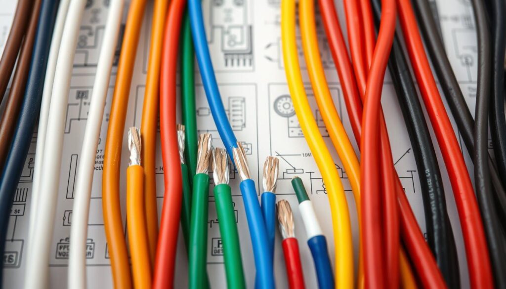
To work safely with electrical systems, it’s vital to comprehend the wiring colours used in UK single-phase installations. A single-phase connection typically features brown live wiring, blue neutral wiring, and green/yellow earth wiring, with a voltage difference of 230V between the live and neutral wires.
Identifying Live, Neutral and Earth in Modern Installations
In modern UK single-phase systems, you’ll encounter brown live wires carrying 230V, blue neutral wires completing the circuit, and green/yellow earth wires for safety. It’s crucial not to confuse the blue neutral and green/yellow earth connections.
Practical Tips for Wire Recognition
- Always turn off the power at the consumer unit before beginning any electrical work to prevent shock hazards.
- Use a voltage tester to verify that circuits are dead before touching any wires.
- Pay special attention to the positioning of wires in outlets and fixtures.
Essential Safety Precautions
When connecting new fixtures or appliances, ensure the brown live wire connects to the terminal marked ‘L’, blue neutral to ‘N’, and green/yellow earth to the earth terminal. In older properties, be cautious of mixed colour standards, which may require professional assistance.
Understanding Three-Phase Wiring Colours
The UK’s three-phase electrical systems rely on a standardized colour-coding system for wiring, which is essential for electricians to comprehend. This system is particularly relevant in commercial and industrial settings where three-phase power is used to support heavy machinery and equipment.
Brown, Black, and Grey Live Wires
In three-phase systems, the live conductors are colour-coded brown, black, and grey to differentiate between the three live wires (L1, L2, and L3). This colour-coding is critical for ensuring that electricians can identify and connect the wires correctly.
Blue Neutral and Green/Yellow Earth
The neutral conductor in three-phase systems remains blue, providing consistency with single-phase systems. The earth conductor is identified by its green/yellow striped pattern, ensuring that it is easily recognizable. “The use of standardized colours for neutral and earth wires is crucial for safety,” as emphasized by electrical safety experts.
Applications in Commercial and Industrial Settings
Three-phase systems are predominantly used in commercial buildings, factories, and large installations where the demand for power is significant. Understanding the wiring colours in these systems is vital for electricians and maintenance personnel to ensure safe and efficient electrical operations. The standardized colour system facilitates the quick identification and troubleshooting of issues in complex installations.
Dealing with Mixed Old and New Wiring Systems
Dealing with hybrid electrical installations requires careful identification and management of both old and new wiring colours. When you encounter mixed wiring systems, it’s essential to take extra precautions to ensure electrical safety.
Identifying Hybrid Installations
You can identify hybrid installations by looking for a mix of pre-2004 and post-2004 wiring colours. These may include both old red, black, and green wires alongside newer brown, blue, and green/yellow wires.
| Wiring Component | Pre-2004 Colour | Post-2004 Colour |
|---|---|---|
| Live Wire | Red | Brown |
| Neutral Wire | Black | Blue |
| Earth Wire | Green | Green/Yellow |
strong>Key Safety Measures
- Always use a voltage tester to verify the function of each wire rather than relying solely on colour identification.
- Apply appropriate sleeving or labels to clearly mark the function of each wire according to current standards.
- Document any mixed wiring systems thoroughly, creating detailed diagrams for future reference.
Safety Precautions When Working with Mixed Systems
When working with mixed wiring systems, always verify the function of each wire using a voltage tester to avoid electrical shock or other hazards.
Proper Marking and Labelling Techniques
To ensure clarity and safety, apply clear labels to wires in mixed systems, indicating their function according to current UK wiring standards.
Common Wiring Mistakes and How to Avoid Them
When working with electrical wiring, it’s crucial to avoid common mistakes that can lead to severe consequences. Incorrect wiring can result in electric shocks, appliance damage, and even fires, posing a significant risk to safety.

Incorrect Wire Connections
One of the most dangerous mistakes is mixing up live and neutral wires, potentially causing appliances to remain electrically charged even when switched off. This error compromises the intended function of the wiring, leading to hazardous situations.
Poor Insulation Practices
Inadequate insulation or poorly secured connections can expose wires, creating shock hazards and potential short circuits. Ensuring proper insulation practices is vital for maintaining electrical safety.
Neglecting Earth Connections
Failing to connect the earth wire properly compromises the safety system designed to protect users from electrical faults. A correctly connected earth is essential for preventing shock risks.
To avoid these common mistakes, consider the following key points:
- Mixing up live and neutral wires can lead to dangerous situations.
- Inadequate insulation can expose conductors, creating shock hazards.
- Neglecting to connect earth wires properly increases shock risks.
- Overloading circuits can cause overheating and potentially trigger fires.
- Using incorrect wire gauges can lead to overheating and voltage drops.
- Failing to identify wires in complex circuits can cause confusion during maintenance.
- Rushing through electrical work without thorough testing increases the likelihood of dangerous errors.
By understanding these common wiring mistakes, electricians and DIY enthusiasts can take necessary precautions to ensure electrical safety.
Step-by-Step Guide to Wiring a UK Plug Correctly
To ensure electrical safety, it’s essential to understand how to wire a UK plug properly. Wiring a plug is a fundamental task that requires attention to detail and adherence to safety standards.
Preparing the Wires
Begin by carefully removing the outer sheath of the cable to expose the coloured wires. Ensure you have enough wire length to work with without excessive exposure.
Connecting to Correct Terminals
Connect the wires to their respective terminals: brown (live) to ‘L’, blue (neutral) to ‘N’, and green/yellow (earth) to the earth symbol (⏚). Ensure all connections are secure.
| Wire Colour | Terminal |
|---|---|
| Brown | Live (L) |
| Blue | Neutral (N) |
| Green/Yellow | Earth (⏚) |
Securing the Plug Safely
Once the wires are connected, close the plug casing, ensuring no bare wires are exposed. Verify that the correct fuse is installed based on the appliance’s requirements.
Tools Required for Safe Wiring
Before starting, ensure you have the necessary tools: wire cutters/strippers, screwdrivers, and a voltage tester.
UK Wiring Regulations and Compliance
Compliance with wiring regulations is not just a legal necessity, but a critical safety measure. The UK’s electrical wiring regulations are outlined in the British Standard BS7671 (BS7671), which provides comprehensive guidelines for electrical installations.
British Standard BS7671 Requirements
The BS7671 standard outlines the safety requirements for electrical systems, ensuring that installations are safe for use. It covers aspects such as design, installation, inspection, and testing procedures.
| Aspect | Description |
|---|---|
| Design | Proper planning and design of electrical installations |
| Installation | Correct installation practices to prevent electrical hazards |
| Inspection & Testing | Regular inspection and testing to ensure ongoing safety |
Legal Implications of Non-Compliance
Non-compliance with BS7671 can lead to serious consequences, including invalidated insurance, criminal prosecution in case of accidents, and potential liability for damages. It is a legal requirement under the Electricity at Work Regulations 1989.
Staying Updated with Regulation Changes
Professional electricians must stay updated with regulation changes through continuous professional development and certification. This ensures that electrical work is carried out to the highest safety standards.
Professional Testing and Certification
To guarantee the safety and functionality of electrical appliances, regular professional testing is necessary. This process is crucial for identifying potential hazards and ensuring compliance with safety regulations.
PAT Testing Overview
Portable Appliance Testing (PAT) is a systematic process that examines electrical appliances to ensure they meet safety standards. PAT testing involves both visual inspections and electrical tests to detect potential issues. While visual checks can identify obvious problems, professional PAT testing includes detailed electrical tests that reveal hidden faults not visible to the naked eye.
When to Call a Professional Electrician
You should call a professional electrician for any complex electrical work or when dealing with persistent electrical problems. Warning signs that indicate the need for professional assistance include frequent circuit breaker trips or appliances that are not functioning correctly.
Documentation and Record Keeping
Comprehensive documentation of all electrical work and testing is essential for legal compliance and future maintenance. PAT testing records should include test dates, results, any remedial actions taken, and scheduled retest dates.
| Test Type | Description | Frequency |
|---|---|---|
| Visual Inspection | Checking for obvious damage or wear | Regularly |
| Electrical Tests | Detailed tests for hidden faults | Annually or as needed |
| Earth Continuity Test | Verifies the integrity of the earth connection | During PAT testing |
Maintaining accurate records and adhering to a regular testing schedule helps ensure electrical safety and compliance with wiring regulations.
Identifying Outdated and Potentially Dangerous Wiring
The UK’s older properties often contain electrical wiring that no longer meets modern safety standards. As a homeowner or electrician, it’s crucial to identify and address these outdated systems to prevent electrical hazards.
VIR and Lead-Sheathed Cables
Older installations frequently feature cable types that are now considered obsolete due to safety concerns. Two such examples are Vulcanised Indian Rubber (VIR) cables and Lead-Sheathed cables.
VIR cables, common in pre-1960s installations, were known for their rubber insulation. However, this insulation degrades over time, especially when exposed to sunlight or high temperatures, leaving dangerous exposed live parts.
Lead-Sheathed cables, while durable and resistant to mechanical damage, are now obsolete due to the health risks associated with lead and advancements in cable technology.

Signs of Deterioration and Risk Factors
Several warning signs indicate deteriorating wiring, including discoloured outlets or switches, burning smells, frequent circuit breaker trips, flickering lights, and buzzing sounds from outlets.
Properties built before 1970 are more likely to have outdated wiring systems that may struggle to handle the power demands of modern appliances.
Recommended Replacement Procedures
When outdated wiring is identified, a complete rewiring is often the safest solution. Professional electricians should ensure the proper disposal of hazardous materials like lead-sheathed cables according to environmental regulations.
Upgrading to modern PVC-insulated cables improves safety and allows for better circuit design and the installation of protective devices like RCDs.
| Cable Type | Characteristics | Safety Concerns |
|---|---|---|
| VIR Cables | Rubber insulation, brittle with age | Exposed live parts, electrical shock |
| Lead-Sheathed Cables | Durable, lead sheathing | Health risks due to lead, outdated wiring systems |
| PVC-Insulated Cables | Modern insulation, flexible | Improved safety, compliant with current standards |
Conclusion
Understanding the UK’s electrical wiring colours is crucial for safety when working with electrical systems. The transition from old wiring colours (red, black, green) to new harmonised standards (brown, blue, green yellow) represents an important evolution in electrical safety practices.
Correctly identifying live, neutral and earth wires is fundamental to ensuring circuits function properly and safely. For complex electrical work, consulting a qualified electrician is always the safest approach. Staying informed about wiring colour standards is particularly important for DIY enthusiasts to avoid confusion and ensure compliance with current regulations.
By following this guide, you’ll be equipped to understand and work safely with UK electrical wiring colours, whether installing a new light fixture or rewiring an entire property.